
Last updated: 15 July 2025: David Green
This web page describes the Pilot ACE computer, which first ran on 10th May 1950.
Anyone revisiting this page will find it much altered. It started life as a way for me to document a Pilot ACE emulator I was writing. Since then I have spoken to a number of people and peered into several archives and accumulated a good deal of information.
The page is now reborn as a resource for the Pilot ACE. Assembled here is all the software and information I have been able to find. The emulator has been relegated to one section.
So far as possible, my Windows based emulator is an historically correct representation of the Pilot ACE, a 'virtual' Pilot ACE computer. The original Pilot ACE is in a glass case in the Science Museum in Kensington, London (see above). Don't touch. But you can still program and play with a replica of the Pilot ACE on your PC, using the emulator.

This document contains the following sections (or aims to - working on it):
1. Introduction.
2. Contents.
3. Some History.
3.1 The Evolution of the Pilot ACE.
3.1 10 May 1950.
3.2 November 29th - December 1st 1950.
3.3 1951-1956.
3.4 Thereafter.
4. The Pilot ACE Structure.
4.1 The Computer Console.
4.2 The Multiplier.
4.2.1 Detailed Operation of the Multiplier.
4.2.3 Unorthodox Uses of the Multiplier.
4.2.3 Example: Counting the non-zero bits in a word.
4.2.4 Circuit Diagrams.
4.3 The Drum.
5. The Pilot ACE Instruction Code.
5.1 Some Notes about Interpreting the Pilot ACE Documentation.
5.2 The Final Code.
6. Pilot ACE Emulators.
6.1 Donald Davies' "Pilot ACE Simulaton Program", 1999.
6.2 A Java version of Donald Davies' Simulator, 2001.
6.3 A Windows-based Emulator, 2006-2019.
7. Programs.
7.1 Program Input.
7.1.1 Initial Card.
7.1.2 Aligning the Scope.
7.1.3 Card Headers.
7.2 Demonstration Programs
7.2.1 The 'Successive Digits' program.
7.2.2 The 'Day of the Week' program.
7.2.3 The 'Smallest Factor' Version 1.
7.2.4 The 'Smallest Factor' Version 2.
7.2.5 The 'Smallest Factor' Version 3.
7.2.6 The 'Bouncing Ball' program.
7.2.7 DEUCE Program ZV02 - Easter Day.
7.2.8 e to 306 decimal digits.
7.3 Aircraft design.
7.3.1 John Denison's Drag Program.
7.3.2 Mike Woodger Programs?
7.4 Matrix Algebra.
7.5 Other Production Programs.
7.5.1 John Denison's Shafts Program.
7.5.2 Program P56.
7.6 Music.
7.7 Games.
7.7.1 Nim.
7.7.2 Draughts.
7.8 Donald Davies' other programs.
8. Subroutines
8.1 Subroutine Library
8.2 Multiplication
8.2.1 Fast Signed Multiplication subroutines
M01-M04.
8.2.2 Unsigned Multiplication M5.
8.2.3 Single Length by Double Length Signed
Multiplication M6.
8.2.4 Single Length by Double Length Unsigned
Multiplication M7.
8.2.5 Double Length Multiplication M9.
8.3 Division
8.3.1 Non-restoring division Version 1.
8.3.2 Non-restoring division Version 2.
8.3.3 Non-restoring division (extracting
two digits per cycle).
8.3.4 Integer division.
8.4 High accuracy (e.g. Double length arithmetic).
8.4.1 Double length signed division (H1).
8.4.2 Double length multiplication (H2).
8.5 Floating arithmetic
8.5.1 Floating Binary Point.
8.5.2 Prepare in Floating Form.
8.5.3 Floating Addition and Subtraction.
8.5.4 Floating Multiplication.
8.5.5 Floating Division.
8.6 Square Root.
8.7 Power series
8.7.1 Subroutine K1.
8.7.2 Using K1 to calculate ln(1+X),
(0 ≤ X ≤ 1).
8.8 Read, Card Input
8.8.1 Subroutine R1.
8.8.2 Subroutine R2.
8.9 Output, punched cards
8.9.1 Subroutine P1, Punch Decimal
Number
8.10 Random Number Generator.
8.11 Trigonometrical functions
9. References
9.1 Pilot ACE
9.2 DEUCE
9.3 General
9.4 Sources
9.4.1 The NPL Archive.
9.4.2 AlanTuring.net.
10. Notes
10.1 The Initial Card.
10.2 Wilkinson's 1955 non-recurring Division
Code.
10.3 Donald Davies'
"Pilot ACE Simulaton Program".
10.4 A Java version of Donald Davies' simulator.
11. The Fine Print - Permissions
12. More Fine Print - Disclaimer
The ACE Pilot Model was designed and built at the National Physical Laboratory, Teddington in England. According to Donald Davies, "The main honours for the design and construction of the Pilot Model ACE are shared by Alan M. Turing, James H. Wilkinson and Edward A. Newman, aided by a sharp nudge from Harry D. Huskey, who really started the Pilot Model idea rolling." [CJ05 ix]
The ACE computer was Alan Turing's brainchild. You can find a lot more about Alan Turing in the web-site maintained by Jack Copeland and Diane Proudfoot. Turing started to design the machine in 1945 after the close of the Second World War. He envisaged a large, sophisticated computer. In 1947 the visiting American mathematician Harry Huskey proposed building a small Test Assembly to prove the concept. This project, designed to be as simple as possible while still producing a functioning computer, started in the spring of 1947 but was abandoned. The idea was revived in 1949, renamed as the Pilot model ACE, first worked on 10th May 1950 and was completed in 1952.
The full story of the conception and construction of the Pilot ACE can be found in Copeland's book "Alan Turing's Automatic Computing Engine" [CJ05]
The Pilot Ace evolved through several stages and the instruction codes and console layout changed several times. The changes to the console can be seen in the succession of photographs displayed in the emulator picture gallery.
The console layout used in the emulator depicts the console now preserved in the Science Museum in London (below) and the instruction code is the version described by Wilkinson in [WJ55].

It is convenient to start our story with the eventful day when the machine first ran a program.
"Towards the end of the day on 10th May 1950 we had all the basic pulse circuits working, the control unit, one long delay line and a short delay line fitted with an additive and subtractive input. However, our only method of inserting instructions was via a set of 32 switches on which we could set up one instruction at a time in binary; our only method of output was a set of 32 lights to which a binary number could be sent".
"Unfortunately the amplifier on the delay line was barely adequate and the probability of remembering a pulse pattern for as long as a minute was not very high. We concocted a very elementary program consisting of a few instructions only; this took the number on the input switches, added it into the short delay line once per millisecond and put on the next light on the set of 32 output lights when the accumulator overflowed. The lights therefore came on at a speed which depended on the size of the number on the input switches. We laboriously fed this program again and again into the computer but each time the memory would fail before we could finish. On about the twentieth occasion we finally succeeded in inserting the whole program and all the lights flashed up instantaneously. We reduced the input number and they came on slowly one by one; we doubled it and the lights came on at twice the rate and we switched off for the day knowing the computer was working." [WJ05 99]
If you would like to relive the events of that day (but with a more reliable delay line), see the 'Successive Digits' program.
"The first Pilot ACE program became known as 'Suc Digs'. It was designed to test out the loading and operation of instructions, the single length accumulator TS16, input and output of a simple kind, both kinds of jump instruction and shifting in TS26. This simple program became the last resort when testing the machine after a failure. If it couldn't do 'Suc Digs', it was in a poor state, so 'Suc Digs' became an institution." [DD2].
By November, the ACE Pilot Model was working well enough for N.P.L. to risk a grand public demonstration. Day 1 for the popular press produced stories about the 'electronic brain'. Day 2 was for the technical press and day 3 for invited guests including F.C.Williams, Tom Kilburn and Maurice Wilkes.
"Most early computer builders have a 'hard luck story' for their first demonstration day. Ours was a good luck story. For the demonstration we had three main programs, two popular and one serious. Of the popular programs the first [the 'Day of the Week' program] took a date in decimal from input keys and gave out the corresponding day of the week on a cathode-ray tube while the second [the 'Smallest Factor'] took a six-figure decimal number and gave its highest factor. Popular programs provide a merciless test since the slightest error is readily apparent. The serious program traced the path of rays through a complex set of lens; it was virtually impossible for anybody not intimately connected with the computer to know for certain whether this was working correctly. In the event the Pilot ACE worked virtually perfectly for the whole of the demonstration period." [WJ05 100]
"The 'popular' program took in a six figure decimal number and 'gave its highest factor'. Since the output allowed only numbers up to 999, I think it was actually the smallest factor. A bottle of beer was offered to the press for finding any six figure prime. Whenever a multiple of three or seven was called out, Wilkinson responded 'divisible by 3' or 'divisible by 7' before it was entered. This amazed the press more than the machine itself." [DD2]
By December 1950, The Digital Computer Newsletter (Office of Naval Research) was able to report that Pilot ACE had "been used for a number of simple problems, such as the evaluation of the integral of 1/(1+x2) from 0 to 1, integration of Bessel's equation for J0, and tabulation of primes up to 128,000, using a program division routine. It has also been used to solve a problem posed by Dr. Wijngaarden of the Mathematical Centre, Amsterdam, who needed to know whether the number 150,450,047,999 was a prime. The machine found the two factors 1319 and 114,063,721, each of which is a prime. (1950Dec-DigitalComputerNewsletterv2n4.pdf)
"The Pilot ACE had been designed purely as an experimental machine with the object of demonstrating the competence of the team as computer engineers. It was originally intended that when it was successfully completed a full-scale computer would be built. In the event it did not work out like this. At the time when it was successfully demonstrated it was the only electronic computer in a government department and indeed the only other working computers were EDSAC at Cambridge, SEAC at the National Bureau of Standards and an early version of the Manchester machine. We naturally came under very heavy pressure to use the Pilot ACE for serious computing. We accordingly embarked on a small set of modifications which included the addition of an automatic multiplier and improvements to the control unit which made programming a little less arduous. The computer was then put into general use and did yeoman service for a number of years." [WJ05 100]
In February 1952 the Pilot ACE was moved to the Mathematics Division of N.P.L. and put into continuous service. By March 1954 it had been enhanced by the addition of a magnetic drum memory.
Although not intended to be used for large-scale computation, it was in active operation until 1956.
The final version of the Pilot Ace now stands in a glass case in the British Science Museum in London, for all to see.
"During the period when the Pilot ACE was being built the English Electric Company became interested in electronic computers and a small group from the company joined us at N.P.L. ... After the success of the Pilot machine English Electric decided to gain experience by building engineered versions of this computer." [WJ05 102]
"DEUCE (Digital Electronic Universal Computing Engine) is a machine built by the English Electric Co. Ltd., from a design used by N.P.L. for the ACE Pilot Model (Automatic Computing Engine). The differences between DEUCE and the ACE Pilot Model concern certain rationalisations of design and the size of store." [EE59 7]
The first DEUCE was delivered in the spring of 1955. It is fortunate that early DEUCE models were very similar to the Pilot ACE because some documentation for the DEUCE 'Version 0' survives, and provides a valuable guide to undocumented features of the Pilot ACE.

Thereafter, English Electric upgraded DEUCE in several ways. Within a few months they introduced the Automatic Instruction Modifier (AIM). Later they made it possible to read 64 columns of each card rather than 32 (and hence two instructions per row rather than the original one instruction per row). Later still, they made it possible to utilise all 80 columns of a card and also increased the memory size by the addition of seven extra delay lines.
The successive models were called the Mark 0, Mark I, Mark II and Mark IIA. By September 1961 there were two Mark 0, 19 Mark 1, five Mark 2 and four Mark 2A machines in service.
Meanwhile, work finally began on the 'Big' ACE in the autumn of 1954. It was completed in late 1958 and remained in service until 1967. Only one was made. [CJ05 77]
Return to Contents
The multiplier on the Pilot ACE was only partly automatic. It produced the product of two numbers which it treated as positive integers. To multiply two numbers, a and b, together, a was sent to TS20, b to DS14 odd, zero to DS14 even and a transfer (source irrelevant) made to destination 19. The product was then produced in DS14 in about two milliseconds. Corrections had to be made to the answer if a and b were signed numbers.
Because multiplication was used so often, great efforts were made to develop efficient subroutines. Several have survived and are shown in Section 8.2.
The multiplier calculated in parallel with other operations so it was possible to access D20, S14, D14, S13, and D13 during multiplication, and to modify TS20 by transferring numbers to it from DL10, using TCA on. This made possible rapid conversion from binary-coded decimal to binary; conversion of card row patterns to binary; re-arrangement of word patterns; and the counting of digits in a word. These procedures are described in DEUCE News 36, but probably they were implemented only on DEUCE. [DN36]
While no surviving code for Pilot Ace uses TCA there are hints it may have been tried.
Martin Campbell-Kelly in his 1981 paper mentions: "A fascinating item is a note book entitled "ACE News" which was circulated among Pilot ACE programmers for them to record and pass on interesting programming tricks they had discovered. Over a period of years a whole folklore of programming for the Pilot ACE was recorded in this book." [MC81 p137]. I bet there would have been something in there about the multiplier. I have hunted high and low for this book. It isn't in the archive at Wroughton. I hate to think it has ended up in a tip somewhere. Mike Wetherfield mentioned "the various nefarious programming practices known as "frigging the Multiplier" developed for DEUCE. I guess we shall never know if Munday tried to "frig the Multiplier"
John Boothroyd described the behaviour of the multiplier better than I might hope to in Appendix 1 of DEUCE News 36 DN36. What follows is his description, with the sources and destinations adjusted to the Pilot ACE code.
The initial conditions for normal multiplication are
The top (P32 position) digits of the word in 141 are examined at the end (P32 time) of each ODD minor cycle. If the top digit is a zero nothing is added in the following even minor cycle to the contents of 140 shifted up one place. If the top digit is a one, this one is rubbed out and becomes a zero and the contents of TS20 are added to the contents of 140 shifted up one place, in the following even minor cycle.
Denoting the nth partial product in 140 by Xn, the (n+1)th partial product is
Xn+1 = 2Xn + a33-(n+1)B, [a33-(n+1) = 0 or 1]
where B is the multiplicand and the digits of the original multiplier are a1 a2 ... a32 with a1 in the least significant position.
As the contents of 140 emerge in any even minor cycle they are shifted up one place before passing the addition circuits and re-entering 140.
The following table shows the minor cycles in which the various digits of 141 are examined together with the words emerging from and re-entering 140.
The multiplier is a1, a2, a3, ... a31, a32 and the multiplicand is b. Multiplication starts in minor cycle m.

Boothroyd (in DN36) described "various techniques which exploit the logical structure of the DEUCE multiplier and divider for purposes other than straight-forward multiplication and division." Pilot ACE did not have an automatic divider, but as DEUCE used the Pilot ACE multiplier, the multiplier techniques described in DEUCE News 36 were equally applicable on Pilot ACE.
Boothroyd's "rules" for exploiting S14, S13, D14, D13, and D20 during multiplication were as follows (DN36, sheet 31):
The following example, derived from the DEUCE code, shows how it might have been done.
Recasting DEUCE News, page 11: the counting can be done in one or two ways. The method used here produces, separately
Use is made of the ability to extract information from S14 while the multiplication is in progress.
The digits of the input word are sensed in the odd minor cycles starting at P32. If P32 is present, add P1 into 140 in the next even minor cycle. If P31 is present, add another "one" to the count in 140. The original digit in 140 has moved up one place since it was inserted and the units position of the counter is now in the P2 position. The "one" which scores the presence of a P31 has to be a P2.
In this example, counting is performed at two places in 140, P1 and P17. Both counters move up and half way through MULT we have the sum of the more significant 16 digits, SM, at the P16 and P32 positions in 140. At the end of MULT we have the sum of the least significant 16 digits, SL, at P16 in 140, the sum of all digits SA at P32 in 140,1 and SM has now moved up to P16 and P32 positions in 140 (most of the P32 part has been lost). SM at P16 and P32 positions is extracted half way through MULT, and subtracted from 140 at the end of MULT.
DL10 contains
10m P1 + P17
10m+2 P2 + P18
10m+4 P3 + P19
...
...
10m+30 P16 + P32
and the instructions are
0 - 21 TCA on
n - 141 n into accumulator 141
28 - 140 clear 140
0 - 19 start multiply (m.c. m)
140 - 26 (m.c. m+33)
19 - 26 multiply by 2
14 - 13 double (multiply by 2)
141 - 27
22 - 141 (TS26) OR (TS27) into 141
The result is
SA at P1 in DS141
SL at P17 in DS140
SM at P17 in TS26
Five circuit diagrams of the multiplier have survived but it is not known if the latest one is the final version. They were preserved by Betty Curtis and are now held at Bletchley Park.
The five diagrams were designed by G C Alway and drawn by A Roberts. They are reproduced here, courtesy Bletchley Park:
The documents that survive are mostly undated. This matters because the instruction set changed several times during the development of the ACE.
A further complication occurs in Wilkinson's paper for the Royal Society written in 1955 [WJ55]. There he avoids the confusion caused by having the least significant digit on the left and describes the Pilot ACE as though the least significant digit of numbers is on the right, where people commonly encounter it. He also refers to digit positions P1 to P32 as P0 to P31. So care is needed in relating the paper to other descriptions of the machine.
I can no longer find a reference to the simulator on the Web so I have provided a mirror here.
"The simulation is programmed in Visual Basic, Version 1, which is no longer available as a product, but the program can be copied and distributed together with enough software to run it in a Windows environment. It should be easy to adapt it for a current Visual Basic system."

He notes several "deficiencies of the simulation":
"1) The multiplier. Used in the correct way, the multiplier of the simulation gives the correct result but the time it occupies is ignored. A strict simulation would allow the programmer to interfere with its operation by accessing DS14, though this was very rarely used. The ability to run programs in parallel with the multiplier makes it quite difficult to include the multiplier's effect on total time. It could simply occupy 2 major cycles as a rough estimate, but this would misrepresent the parallelism. In the simulation, a check is made that TCB is off and DS14 even is cleared, though the real machine did not do this, it would simply make errors.
2) The drum. No attempt is made to account for the delay imposed for head shifting and the 9 ms taken by transfers. This could be done if the time allowed for head shifts was known as well as the precise nature of the interlock (what things the interlock prevents).
(The simulation gives the elapsed time of the real machine accurately from the entry into a program to its completion if the multiplier, drum or cards are not used within the program.)
3) Strange instructions. The simulation has been tested with instructions such as are commonly found in programs. The example of TS20 when TCA=1 showed how easy it was to make a mistake which affected only a few kinds of instruction (in that case 20-10). It is possible that some unusual instructions exist which are not properly covered. No attempt was made to deal with 'pathological' use of instructions.
4) Card reading and punching. The operator's work of selecting and assembling a pack of cards for the reader cannot be simulated. In the simulation, the card images for input must be assembled in the files devoted to cards (numbers 128 to 383 in our scheme) and the number of the first card given in a text box. Punching produces card images with numbers in the range 256 to 383. This may overwrite existing 'punched' cards. Manual operations to copy sets of 32 words between delay lines and cards make useful card manipulations possible, but it is very different from the real thing.
The T.I.L. source will work correctly only if it is tested after the stop instruction which reads or punches a card row. Outside the time of card operations it usually gives ones.
5) Realism. Because a programmed display of all the store is necessarily very slow, the useful facility of looking at memory during running is lost. Only the output register can be seen during a run. Initial input does give a glimpse of progress, however.
At present, Visual Basic makes it impossible to have a clean halt from a running program.
The controls look nothing like the real machine. This could be remedied with extensive use of graphics, but not by me. Some Pilot model facilities such as stopping on partially specified instructions, are missing.
The simulation has manual features not present in the real machine, such as loading words into delay lines and registers and transfers between delay lines and drum tracks or card images. Words cannot be seen in 'backwards binary' form but are available in hexadecimal, decimal and instruction format. In practice, program preparation, loading and testing and changes during testing are very easy with this simulation."
In 2001, two graduates - Shih-Yun (Athena) Huang and Nick Rugai - at the Department of Computer Science, University of San Francisco, CA. completed a Master's Project, PACES (Pilot Model Automatic Computing Engine Simulation).
They updated Davies' simulator from Visual Basic to a Java application (and also a Java applet). While doing so, they "improved two functions from [the] VB simulator: (1) Run simulator in real pACE time. (2) Display all the delay lines". It seems there is no longer any reference to this project on the Web.

Regrettably the emulator is not currently available. The earlier version will not work on Windows 8 or later. I am currently updating the code.

Quick Operating Instructions to see the emulator work.
To Install the emulator:
If you haven't already done so, create a folder C:\PILOTACE using Windows Explorer. Unzip the contents of the Emulator Package into this folder. The emulator and its support files should all be in C:\PILOTACE. The emulator expects to find its files in that folder and it puts output files there.
To Start the emulator:
The menu bar offers several options, including more pictures of Pilot ACE at various stages of its development and some useful information.
To Run the emulator:
To Run the Demonstration Program 'Successive Digits':
'Successive Digits' was the first program to run on the Pilot ACE, back in 1950.
This program can be run from the card deck SUCDIGS.CRD, as follows:
1. 'Load' SUCDIGS.CRD (in the Menu, click 'Card Handling' > 'Load an Input Card Deck' > 'Open...', select SUCDIGS.CRD (single click on it) and press the 'Open' button.
2. Press (click just below) the 'Initial Input' key in the Card Reader Insert. The cards will read in and the program will stop with {1 25-26} on the Input Statisicer lights (that is to say, NIS = 1; SOURCE = 25; DEST = 26, remembering that the numbers have their least significant digit on the left)

3. Set P22 to one on the ID. (Press the corresponding black key near the bottom of the screen)

4. Press the 'ONE SHOT' key. The OS lights will gradually turn on in sequence.
5. The program will stop on (1 25-26}, ready to repeat the calculation.

6. To go again, press the 'CLEAR OPS' key to clear the OS, then return to step 3.
P22 works well on my computer but you may wish to try different speeds by choosing different P values. The larger the number, the faster the OS neons will light up; the lower, the slower; so you can experiment to find a speed that suits your computer. The P numbers can be altered while 'Suc Digs' is running. To turn off a bit on the ID, raise the corresponding black key (click just above it).
To quit the emulator:
Return to Contents
Many programs were written for the Pilot Ace. Few have survived.
"Problems dealt with during 1952 included bomb trajectories, aircraft flutter calculations, a gravimetric survey, reduction of aerial survey data, pressure distribution on aircraft wings and testing a theory on geomagnetism." "During 1953 the work for aircraft firms continued to expand, and the final stage of the flutter problem - the calculation of critical speeds - was programmed. Solutions of stereograms (in the analytical treatment of photogrammetry) were undertaken for the Ordnance Survey Office; the machine was used in a investigation into the optimum setting of traffic signals under varying traffic conditions; an investigation was undertaken into the stability of particle orbits in the proposed synchrotron of C.E.R.N at Geneva."
And many more projects followed. None of this material has survived, except for the following:
Many of the earliest DEUCE programs were simply transcribed from Pilot ACE code into DEUCE code, often at N.P.L., so reverse coding them produces routines that are probably very close to the originals. I have done this for .
The first of his programs, written between December 1952 and March 1953, is particularly well documented, with flow charts, coding sheets and a worked example. It calculates the drag on the fuselage of an airplane and most likely contributed to the design of the English Electric Lightning fighter jet (the first English airplane to exceed the speed of sound in level flight). It is reviewed here in Section 7.7.
His second program, written in mid-1953, relates to the critical speed of machinery. The file is labeled "Part A: Theory and Programmes" suggesting there may have been examples in a Part B, but if so that is now lost.
On the Pilot ACE, the procedure to read in a new program was to select the appropriate deck of cards, place the cards in the hopper of the card reader, and then press the 'Initial Input' key.
"The machine is started by operating a switch [the Initial Input key] which clears all the registers and artificially operates the read feed." [WJ51B 33]
An Initial Card is needed because there is no reason to call any particular minor cycle m.c.0. When the Initial Input key is pressed the computer is able to align with the start of a word, but that word may be in an even or an odd m.c. The machine can always distinguish between even and odd because of the structure of DS14. The delay lines need to be in sync with DS14.

On DEUCE, "When the Initial Input key is pressed the memory store is cleared, i.e. every word is zero. For some reason connected with the circuitry TSCOUNT is not completely cleared; instead the word {0, 0-0, 0, W, T, X} is left in it." [**EE59 87]
There is no record of whether the English Electric engineers introduced this 'error' with their circuit changes or if it was already present in the Pilot ACE. Quite possibly it was in the Pilot ACE, because it would not have caused a problem.
Fortunately two actual cards exist in the Science Museum archives. They are identical and have this content:
rowY    {0  0-23    0  0 X}
rowX    {0  0- 0    0  0 X}
row0    {0 29-14    0  1 X}
row1    {0  0- 0    0  0 X}
row2    {0 25-13    0  0 X}
row3    {0  0- 0    0  0 X}
row4    {0 14-25    0  1 X}
row5    {0  0- 0    0  0 X}
row6    {0  0-21    0  1 X}
row7    {0  0- 0    0  0 X}
row8    {0 28-14    0  2 X}
row9    {0  0- 0    0  0 X}
Assume the worst case: after initial input, TSCOUNT contains {0 0-0 W T X}
If P1 is added to DS14(1), DS14(1) will become zero and there will be a carry of 1, which will be lost. So DS14(0) will remain equal to -1. Thus DS14 is non-zero if m+T+13 is odd.
If P1 is added to DS14(0), DS14(0) will become zero and there will be a carry of 1. The nature of double length arithmetic using DS14 is that a single length transfer to DS13(0) will automatically extend the carry to DS14(1). Thus the carried 1 will be added to DS14(1), setting DS14(1) equal to zero also. Thus DS14 is zero if m+T+13 is even.
If DS14 is non-zero, the next instruction is DL11(m+T+19), which is odd, and {0 0-0 0 0 X} is sent to TSCOUNT in m.c. m+T+19. Set n=m+T+19. n is odd.
The machine is now in a standard condition to read the remaining cards - TCA and TCB are OFF, {0 0-0 0 0 X} is in TSCOUNT and m.c.0 is even.
However, m.c.0 may not be aligned with the top of the scope.
P35 is also present on row 9, and this stimulates the reader to read another card.
Return to Contents
As mentioned earlier, this was the first program to run on the Pilot ACE, on 10 May 1950. The original version of the program is lost and would anyway have used the instruction codes current in 1950.
In 1999, Donald Davies recreated the code using the 1955 instruction set. "This first program became known as 'Suc. Digs'... The output was a single binary digit, running along the lamps which showed the output register. The rate of travel was adjusted by choosing an input number which was added to the accumulator until it spilled into the sign digit, then making one shift of the output digit. ... There was no record of the [code] we used on the real machine, but [my version of Suc. Digs.] does the same thing - as far as I can remember." [DD2]
I think this is not entirely correct. The nature of the OS is that "If several words are sent to D28, the number set up on the lights will be equivalent to a number which has a one in every position where at least one of the words had a one" [WJ51A #7.2] and "The lights can only be cleared, that is the number registered in them returned to zero, by operating a manual switch" [WJ55 270]. So the output would not have shown a single digit but rather a line of ones gradually building from left to right. And Wilkinson states "we finally succeeded in inserting the whole program and all the lights flashed on instantaneously." [WJ05 99]
This program can be run from the card deck SUCDIGS.CRD (Section 4).
Alternatively, you can repeat the events of 10 May 1950 as follows:
The code in steps 2 and 5-8 is a small boot-strap I have written. (15-15 is a dummy instruction. It does not change the content of memory but the timing number allows the program to put the subsequent code into the correct stores.) This is one way to get the program into the computer, but I don't know if Wilkinson used this code. The code in steps 9-18 is Donald Davies' 'Suc Digs' program.
If you tune the monitor to Delay Line 1 you will see the delay line updated as each instruction is entered.
This was one of the three programs presented at the N.P.L. public demonstration on 29th November 1950. We don't yet have the full code for this program.
"For the demonstration we had three main programs, two popular and one serious. Of the popular programs the first [this Program] took a date in decimal from input keys and gave out the corresponding day of the week on a cathode-ray tube while the second [Smallest Factor] took a six-figure decimal number and gave its highest factor. The serious program traced the path of rays through a complex set of lens; it was virtually impossible for anybody not intimately connected with the computer to know for certain whether this was working correctly." [WJ05 100]
This is the only Pilot ACE program for which some original cards survive. Six original input cards are held in the archive at the Imperial College Library, London. Sadly the deck is not complete: the first card is a special card to initialise the computer and the last two cards are part of an incomplete triad. It seems possible that just one card is missing, and if so, it might be possible to resurrect the original code.
A similar program was written for DEUCE (Calendar, ZV06) but that code is also lost.
Code is available for a later DEUCE version ZV06T/1. However this is a more sophisticated program coded for a much upgraded version of DEUCE and so not a useful guide to what ZV06 might have been. "This demonstration program reads a date (A.D. only) set on the I.D., calculates the day of the week on which it falls and displays the answer in the scope. ... allowance is made for the change from the Julian to the Gregorian Calendar on 3rd - 13th September, 1752. Except on Mark 0 machines this program supersedes ZV06 (No. 5) because it is ... not restricted to the 19th and 20th centuries."
Donald Davies, who was present at the demonstration in November 1950, later recalled that "The program took in a six figure decimal number and 'gave its highest factor'. Since the output allowed only numbers up to 999, I think it was actually the smallest factor. A bottle of beer was offered to the press for finding any six figure prime. Whenever a multiple of three or seven was called out, Wilkinson responded 'divisible by 3' or 'divisible by 7' before it was entered. This amazed the press more than the machine itself."
This code in PROG07DD.CRD was developed by Donald Davies in 1999. "I have tried to reproduce the popular demonstration. ... I have made it to treat any odd number less than 232. Given a number in the input register, it tries division by 3, 5, 7,... until the quotient is smaller than the test divisor. If the remainder is zero, it signals a prime by the buzzer. If not, it outputs the smallest factor of the given number [on the OPS] and returns to the start in either case."
To run the program:
1. Load the program cards PROG07DD.CRD
2. The program stops with (1 0-15) on the IS lights
3. Enter a number on the ID lights (for example, the illustration below).
4. Press 'ONE SHOT'. The computer calculates the smallest factor and puts
it on the OS lights.
5. To make another calculation, press 'CLEAR OPS', press 'CLEAR ID' and go
to step 3.
"A useful number for demonstration is 999,997 which is 757 x 1321". The result for this calculation is shown below.

This would not have been a very usable demonstration. Inputting a six digit decimal number in backwards binary and reading a three digit result in backwards binary would have been incomprehensible to most people. Davies provided input and output in decimal in his emulator but not in the Pilot ACE code.
One way to enter the numbers as decimals is to use 4-bit binary-coded decimal in the ID, and to display the smallest factor in the same way in the OS. I have developed some code to do this in Version 2 below.
Davies noted that "the program took in a six figure decimal number" but there is no record of how this was done.
I have extended the code to allow the decimals to be entered as individual 4-bit binary codes in the ID, and to display the smallest factor in the same way in the OS. This is PROG07DG.CRD.
To run the program:
1. Load the program cards PROG07DG.CRD
2. The program stops with (2 0-26) on the IS lights
3. Enter a number on the ID lights (for example, the illustration below).
4. Press 'ONE SHOT'. The computer calculates the smallest factor and puts
it on the OS lights.
5. To make another calculation, press "CLEAR OPS', press 'CLEAR ID' and go
to step 3.

The numbers in this screen are hexadecimal (four bits separated by a space), reading in the normal way (least significant digit on the right and least significant bit on the right). The silver switches have been adjusted to highlight the position of the separating spaces and do not play an active role in the program. The ID shows the number 999997 and the OS shows its smallest factor 757, with the most significant digits on the left, ie. not in "Chinese binary". The calculation takes about 12 seconds on my computer.
Further investigation reveals that there is a DEUCE program ZV03 'Million Factors Slow', "a demonstration programme [which] reads a number less than a million from the I.D., computes its smallest factor, if any, and displays this, or the word PRIME, in the scope". It is another very early program, DEUCE Program Number 7, so it was almost certainly derived from a similar Pilot ACE version.
For input, "On the I.D. set successively the digits of the number commencing with the most significant; the convention used is for the P1 - P10 keys to represent the digits 0-9. If the number has less than 6 digits set a P32 after the last one.
The "Programme stops on 1, 30-21 X with the smallest factor or the word PRIME displayed in the scope".
ZV03 is a candidate for reverse engineering, as we have the code, but it is not yet implemented.
After the Lord Mayor's Show comes the dust cart. BOUNCE.CRD is a bouncing ball demonstration program. The program was written in 2011 and has no historical significance. However, it is authentic Pilot ACE code. It depicts a ball (in DL 8) bouncing within the confines of the monitor.

To run the program:
1. Load the program cards BOUNCE.CRD
2. Switch the scope to DL 8.
3. The program runs until interupted.
Notice that the ball stays within the vertical boundaries but may run through the top or bottom of the monitor screen. This is perfectly normal (see Note 10.1).
There is no speed control. What you see is what you get.
DEUCE had a demonstration program ZV02. It "reads a year from the I.D. and displays in the scope the date of Easter Sunday in that year".
Cliff Robinson recalled that: "Easter Program: you may be interested in its background. We were due to formally demonstrate DEUCE to the first batch of experts (mainly from NPL) who were due to come to Kidsgrove. About three days before they came, J.K. Brown insisted we invent and make some demo programs to show it off. One of these was the Easter Sunday program written by John Denison. " This event most likely occurred in 1955.
So, clearly, the Easter program was not a Pilot Ace program. However, given the dearth of demonstration programs for the Pilot Ace it is convenient to adapt it to run on the emulator. This Pilot Ace version of the Easter program is described here.
A tray of cards, (NPL I2) in the Woodger/NPL papers in the Science Museum Archives in Wroughton, contains cards output by this program and dated December 1951.
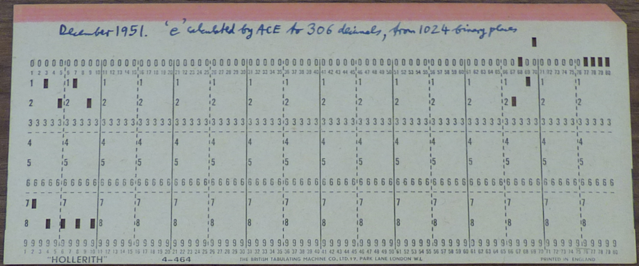
There is no more documentation but I have reprogrammed the calculation and more details are here.
In 1958 John Denison circulated a program called Melody Maker to play music on DEUCE. All that survives of the program is the first sheet of his write-up. There are no flow charts, coding sheets or cards. Even this introduction is probably missing a second page. Melody Maker allowed the computer to become a sort of juke box, with coded tunes stored on the drum and available to be played on request.

I can find no mention in surviving Pilot ACE documents that Pilot ACE played tunes. And John Parks, who helped maintain the Pilot ACE back in the day, told me he had no recollection of hearing it play music. However, it undoubtedly could have done, using an external speaker.
Duplicating John Denison's Melody Maker would serve no useful purpose now but implementing music on the Pilot ACE is an interesting problem. This program shows one way in which it could have been done. Good King Wenceslas" would have sounded something like this: